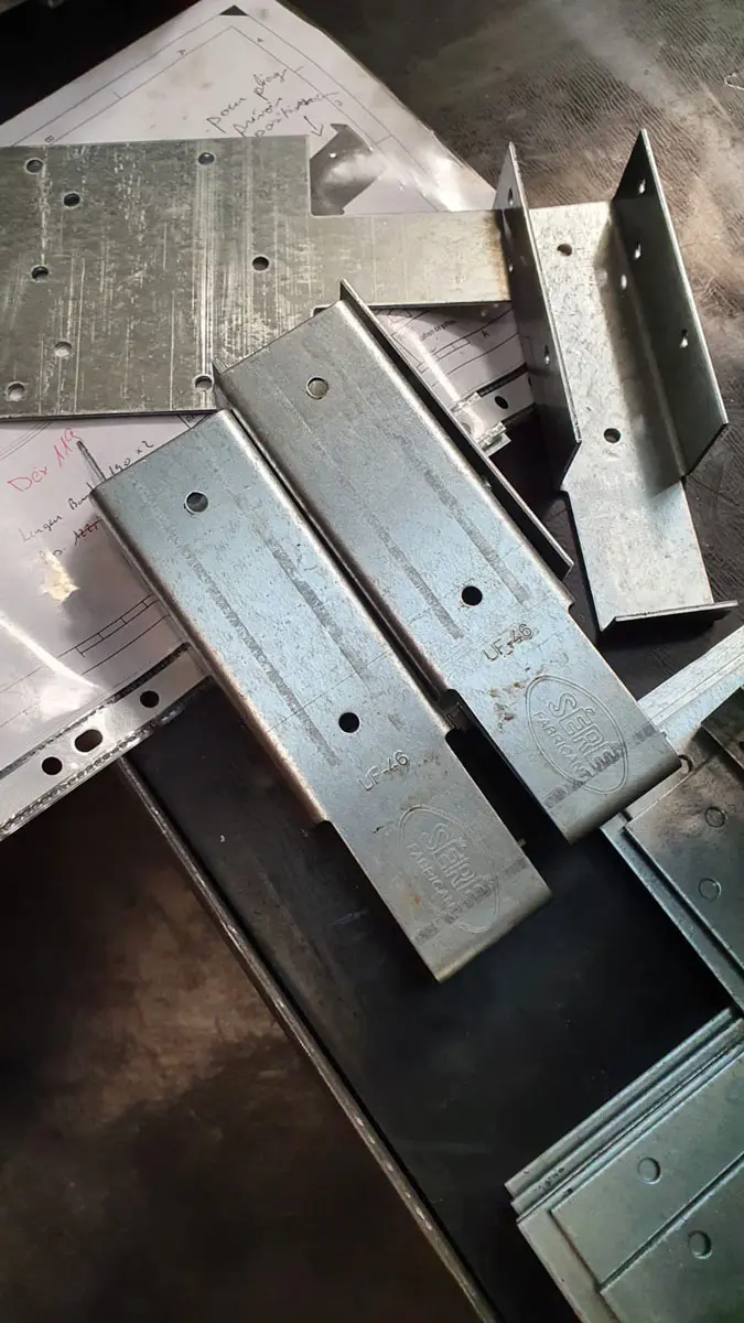
We have been working for several months on a complete range of framework fastening parts for our Client Séré. Let’s explore the stamping and bending process for these parts designed for metal framers.
3D design of the various parts in the framework fastener range, using cutting and sheet metal bending
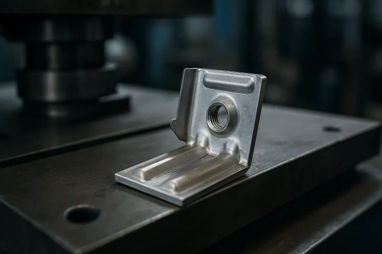
Together with our client, we dimensioned the various parts to meet technical requirements. To achieve this, extensive discussions were necessary to define the client’s expectations and our capabilities in terms of part dimensioning for cutting, bending, and the type of coining that we are able to perform for client logo marking.
Following this design phase, we produced prototypes by laser cutting and bending tooling to verify the part dimensioning after bending.
Metal framework end cap.
Production of framework fastener prototypes under real bending conditions
Following this design phase, we launched prototypes by laser cutting and produced all the elements for the bending tool.
This initially allowed us to validate the custom bending tool based on the different part versions, as well as the assembly of the parts. It also allowed us to send parts to our client for real-world testing.
Metal connection for frameworks.
Production of cutting tools for the cross-shaped part range
Given the size of the parts, we chose to create modular tooling for the cross-shaped parts, featuring a common section and a section with interchangeable cassettes to produce the different versions.
With the same tool, we can produce 4 versions of cut parts to cover all cross-shaped parts for 40 and 60 mm square frameworks. In a single stroke, all cutting operations are performed simultaneously with the coining operations for the logo and part reference.
Given the number of punches and the sizes of the cuts, we planned to perform these cutting operations on our sheet metal decoiling line equipped with a 200-ton press.